build with Rushi |
is a mini building series where I play around with microcomputers and make some cool stuff. This series is archived! Thank you so much for joining me on this journey!
The Code for all episodes is here. |
7. Using Deep Learning to classify Fashion MNIST Images: Image ClassificationSeries Finale - January 3rd, 2021 - Episode 7In the series finale, we will be using deep learning to classify articles of clothing — by using a very popular and well-known dataset: The Fashion MNIST. The Fashion MNIST dataset contains around 70,000 images (60,000 for training, 10,000 for testing) of Zalando's article images (clothing, shoes, bags, accessories..etc.). The dataset contains a target column, containing an associated label (for each example) out of 10 classes. Each image (or row) is a 28x28 gray-scaled image, so in total containing 784 pixels.
We will be building a deep learning model called a Convolutional Neural Network to accurately predict the class of a given input article image (ex. shirt, pants, shoes). This problem is often depicted as the foundational machine learning problem--which can be used in classification of clothing, products in online shopping for example! For the layout of these project “posts” on this page, there will be a short tutorial where I explain the process of building (link is above), and over here I’ll be writing about the planning/thought process! Thanks
IntroductionWe are going to be exploring the world of deep learning and artificial neural networks by building a Convolutional Neural Network (CNN) to classify article images (of fashion accessories). We will be using one of the most well-known datasets when it comes to ML: The Fashion MNIST database. This database consists of article images of types of clothing, shoes, and accessories, and our model's job is to accurately predict what class an unseen input image falls into.
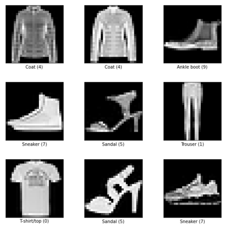
These are some examples of images from the Fashion MNIST dataset:
Some examples from the Fashion MNIST dataset
Software Used
Process + Experimental Analysis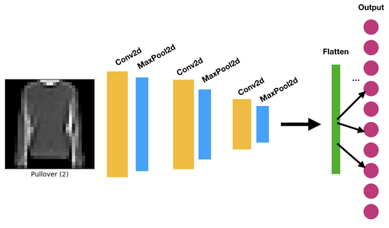
The CNN_Model plan
I decided to go with a Convolutional Neural Network (CNN) in order to extract more details and patterns in the given input image. A certain aspect that makes CNN's unique and more fitting for 2-Dimensional Image data is their Convolutional layer. Convolutional layers essentially use a matrix to 'slide' across the input image to obtain important features in the input. The output of a convolutional layer is the convolution between the sliding matrix and the input -- resulting in a feature map. Each layer can have multiple feature maps to extract multiple different features! Adding more feature maps adds more weights (values in each kernel).
The training dataset size I used was 36,000 samples, and the testing dataset was 10,000 samples. This was also held constant throughout the hyperparamter tuning.
It's important to be careful not to increase the momentum of the optimizer over a certain threshold, since that might lead to overfitting (the model will have a high accuracy value for the training dataset, but low accuracy value for the testing dataset).
After multiple test runs, I reached an accuracy in the high 80s range (~88%). Theories + Conclusion-> I think maybe using more data (instead of just 60% of the 60,000 given samples) might make the model more generalized, since it has seen more examples during training.
-> I also think adding more kernels/filters to extract more details and features that distinguish two similar looking classes from one another could have reached a higher accuracy as well. -> Adding more layers and adding more depth to the network might have also helped in the accuracy This definitely shows that model hyperparameters also play a huge role in reaching a high accuracy rate! This is one of my favorite episodes ever, and we will be concluding this series with the finale. I have enjoyed every single project, and every project has helped me learn something interesting about an aspect in tech/engineering. Thank you so much for joining me on the journey! If you want to know more about the Fashion MNIST: https://research.zalando.com/welcome/mission/research-projects/fashion-mnist/ Code to the Colab Notebook: https://github.com/aarushiramesh/Build_with_Rushi/blob/master/Deep_Learning_Fashion_MNIST.ipynb 6. Building a Grade Calculator using a Python ScriptAugust 25th, 2020 - Episode 6
Back to School season is here, and because school is going to be on a different medium/setting for lots of us, let's get together for this next episode of #buildwithRushi and build a grade calculator to calculate your current grade in any class! This is going to be done using a python script, which is essentially a Python code file which you can execute and run the program!
For the layout of these project “posts” on this page, there will be a short tutorial where I explain the process of building (link is above), and over here I’ll be writing about the planning/thought process, how the circuit works, and anything we can improve on..etc. If you want to follow along and look at the details of the building process, watch the tutorial and then read the rest of this post. It’ll make much more sense, and I encourage you to try it!! HAVE FUN!
IntroductionCalculating grades can be an easier process by using a quick python script to consider the weights and percentages for you!! So today, we will be designing and creating a python script which basically takes in the current grades from tests/assignments you have as inputs -> and calculates the total calculated and current grade in your class (at any particular moment!). Lets get started! Even tho many online systems do this for us, it's always good to double check! :)
"Materials" I Used
The Process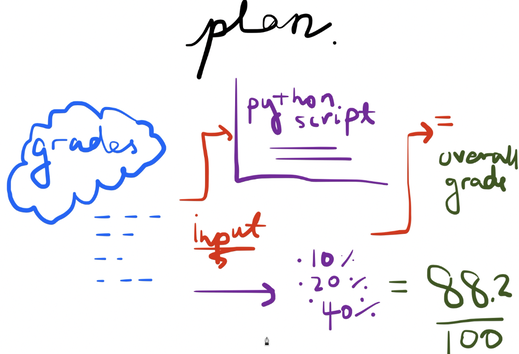
So our entire goal over here is to make a python script which takes in an array of grades as input, processes these inputs and computes the weighted average and sum, and then outputs the current grade in your class/studies to the Terminal! How does this all work though? So essentially the script will accept these inputs as command line arguments. So when you type in the command to execute your script, like python script.py, you also add your grade inputs into the command as well! So essentially the command contains the grades in an array format for each category (quizzes, projects, assignments, homeworks, midterms). For more details about the Python script coding process click here!
The code for the Python script is linked here. ConclusionIt's really nice to have a double check sort of a tool with you to see where you are at in your class! Even if you haven't completed or received grades yet, you could always input in your grades to assignments you have completed so far, compute the weights depending on your class, and get an output! This was so much fun, and making nice and little Python scripts is just the best way to get the hands-on experience with Python! Have fun!!! 5. Ssh'ing into your home computer: ssh Server in your computer4th of July - Episode 5Hello, and welcome back to #BuildwithRushi! It has been a while, but we are back once again!! Hope you are doing well :) So today, we will be setting up an ssh server in a computer at your home!! This is a little project-type experiment! What is an ssh server? An ssh server enables the ssh protocol to establish a connection from a client (your home computer) to the server (the destination computer). Today, we are going to be ssh'ing to our home computer by setting up an ssh server in that computer. This is so that you can access this computer remotely as well (if you don't have direct access to your home/desktop computer, and you want to access it's directory/files, for example!). This one is going to be VERY VERY FUNNNN, so lets get started. :)
IntroductionIf you want to learn about the ssh protocol (Secure Shell), click here for more info! I have always been intrigued by the idea of accessing a device remotely, and accessing all of its directories/information remotely as well. I am going to be setting the server up on a macOS running computer, but I believe the steps are pretty similar with other operating systems such as Unix/Linux, Windows..etc...If you do have a different OS for your computer, I highly encourage you to search it up!
So first off to enable an ssh remote connection in your computer, you should first enable remote login in your System Preferences. Go to System Preferences -> Sharing -> Check Remote Login to enable it. Once this is enabled, an ssh server is set up in your laptop, and you can ssh to your laptop by running this command in your Terminal: ssh'ing to your computer in your local network!
Now, computers in your local network (at your home, for example) can access your computer using ^ that command. To allow access from the Internet, however, you will need to configure your network so that all of the traffic coming from a specific TCP port (port 22) is routed to your Mac laptop. (This will require some configuring :) )
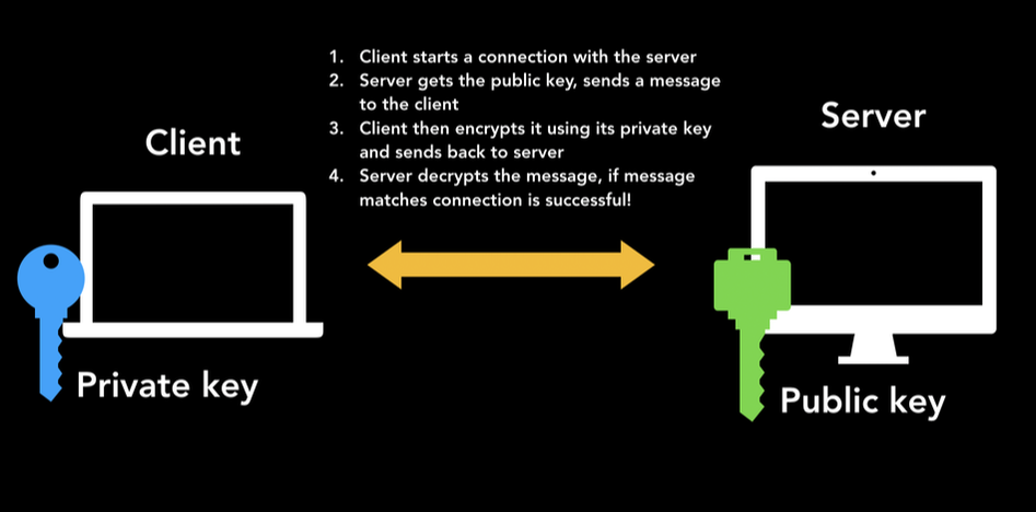
Authenticity of a connection: Public and private keys..To verify the server.....
When you ssh into a server for the very first time, you might see the above commands presented in your terminal. ^ The key fingerprint represents the fingerprint of the server's public key. This basically asks the user to approve the public key, so that it remembers the fingerprint when making the next connection to the same server. This is used to authenticate the host server.
The ProcessSince there isn't a lot of required "planning" for setting up the ssh server it's a very simple process. The whole process basically consists of running some commands on your Terminal to enabling an ssh connection from another device. I also tested this process by ssh'ing into my home computer from another laptop, and it worked!! :) It was amazing to see this connection being enabled, and I highly encourage you to TRY IT!! GOOD LUCK :) 4. SlapJack Card Game Simulator Project: C++ GameMay 26th, 2020 - Episode 4
Welcome to #BuildwithRushi's Episode 4!!! This one is going to be a little different, we are going to be doing some programming today! Today, we will be simulating a very fun game of Slap Jack! SlapJack is a popular and fun card game, where all the cards in the deck are passed around to the players (each player has a pile of cards to start with). The players cannot see their pile of cards, and each player take turns by lifting one card from their pile and placing it in the center. The ultimate goal of the game is to win all the cards, and to do that, you have to be the first player to slap every Jack card that is placed in the center. The player that ends up with the entire deck wins the game! We will be simulating the game of slapjack using C++ classes, and for the sake of simplicity, I'll be designing a 2-player slapjack game.
For the layout of these project “posts” on this page, there will be a short tutorial where I explain the process of building (link is above), and over here I’ll be writing about the planning/thought process, how the circuit works, and anything we can improve on..etc. If you want to follow along and look at the details of the building process, watch the tutorial and then read the rest of this post. It’ll make much more sense, and I encourage you to try it!! HAVE FUN!
IntroductionI wanted to try something a little bit different for this week, so I decided to design/simulate a game of SlapJack! SlapJack has been one of my favorite card games (even though it takes a ridiculous amount of time to actually declare a winner!! LOL). You'll also see this when I run the program, as to how many lines are actually printed out, until we have come to declare the winner. I used C++ to implement this game, since the classes & instances make designing this game very helpful and efficient. Let's get on to it!!
"Materials" I Used
Planning and Thought ProcessSlapJack requires some important components, so lets list them out so we know what functions we need to implement to design the game:
This is my really messy drawing of the implementation: so we are going to be declaring 3 main classes to develop this game - Card class, Player class, and the Deck class. Each class will consist of functions/variables to simulate the actions (presented above). More info is on the video! 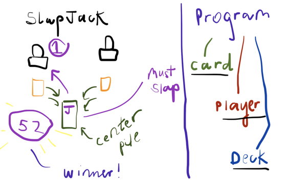
ConclusionThe code for this project is here. I really REALLY enjoyed designing this game! It was really fun! We could also add some graphics as well (there may be a Part 2, HINT HINT), to actually create a fun simulation of this card game. I loved documenting this one, and can't wait to see what's next!! Since I uploaded 3 days late, the next episode will be out on Tuesday, June 2nd! Thanks for watching/reading, and I'll see you next week! Looking forward to it :) 3. Building a 'Light Alarm' System: Photoresistor ProjectMay 16th, 2020 - Episode 3
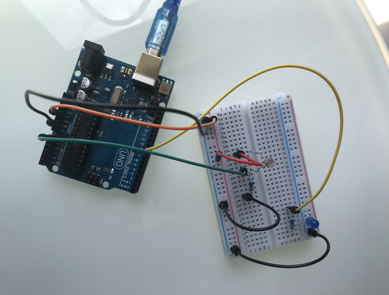
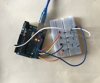
Hello, and WELCOME BACK to #BuildwithRushi episode 3!!!! It feels soooo great to be back again, lets gooo!! Can't believe we are on to the third episode already, lets get started. Today, we are going to be designing a Light Detection/"Alarm" System. This one is going to be an exciting one! So basically our system will turn on an LED when it detects light; if it doesn't detect light, the LED turns off! We will be using a photo-resistor, an Arduino UNO board (for power/voltage), an LED and resistors. Our system can be related to a real life Light Alarm of some sort, since it gathers the inputs (light detection), and converts it into an output (LED turning on), which gives it an alarm effect. Have fun :)
For the layout of these project “posts” on this page, there will be a short tutorial where I explain the process of building (link is above), and over here I’ll be writing about the planning/thought process, how the circuit works, and anything we can improve on..etc. If you want to follow along and look at the details of the building process, watch the tutorial and then read the rest of this post. It’ll make much more sense, and I encourage you to try it!! HAVE FUN!
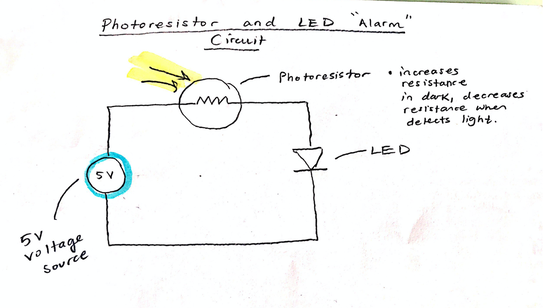
IntroductionWe will be designing a system where when light is detected, our LED will turn on, else, our LED is off. To detect light, we will be using a component photoresistor. A photoresistor is a sensor and light-controlled variable resistor. A photoresistor's resistance changes based on the amount of light it is exposed to. The resistance decreases when the component is exposed to more light, and increases when it isn't. The system we will be designing involves a threshold value. Our system will read in the analog input of the photoresistor: if the analog input surpasses the threshold value (photoresistor has high resistance), the LED is off (because it is not detecting any light). Else, the LED is on (meaning the photo cell is detecting light)!! This makes our system a light detection system! Lets have fun with this one :)
Materials I Used
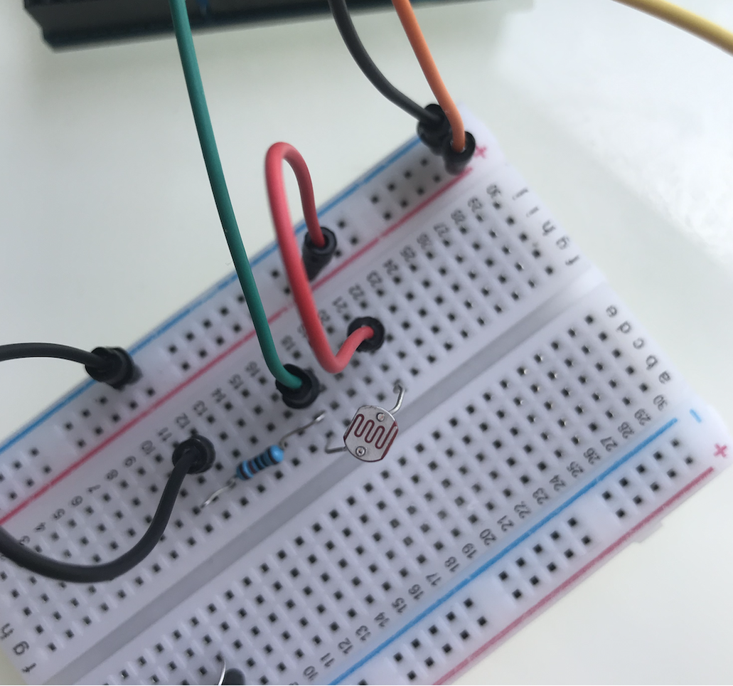
Planning and Thought ProcessInitially, I was planning on building a system incorporating buttons and LEDs, however, I realized I had a photo-resistor with me!! I've always wanted to build a detection system of some sort, so lets get started! The first step was to obviously learn more about this photo-resistor component. How does a photoresistor work? A photoresistor changes its resistance due to the light exposed to it. It is a very small light sensor. The resistance values of a photoresistor when exposed to light typically range from 0-20kohms. And when the surroundings are dark, the resistance reaches a super high value: up to 1 MOhms (Megaohms)!! This is the circuit/system we will be designing:
ConclusionThe code to the project is here. I once again had lots of fun documenting the building process and building the system (of course!!), and I can’t wait for next week's episode!! I’ll be posting the fourth episode next Saturday, May 23rd. Until then, stay safe and wish you happiness and peace! Have fun :) 2. Building a Simple Timer: Seven Segment DisplayMay 2nd, 2020 - Episode 2
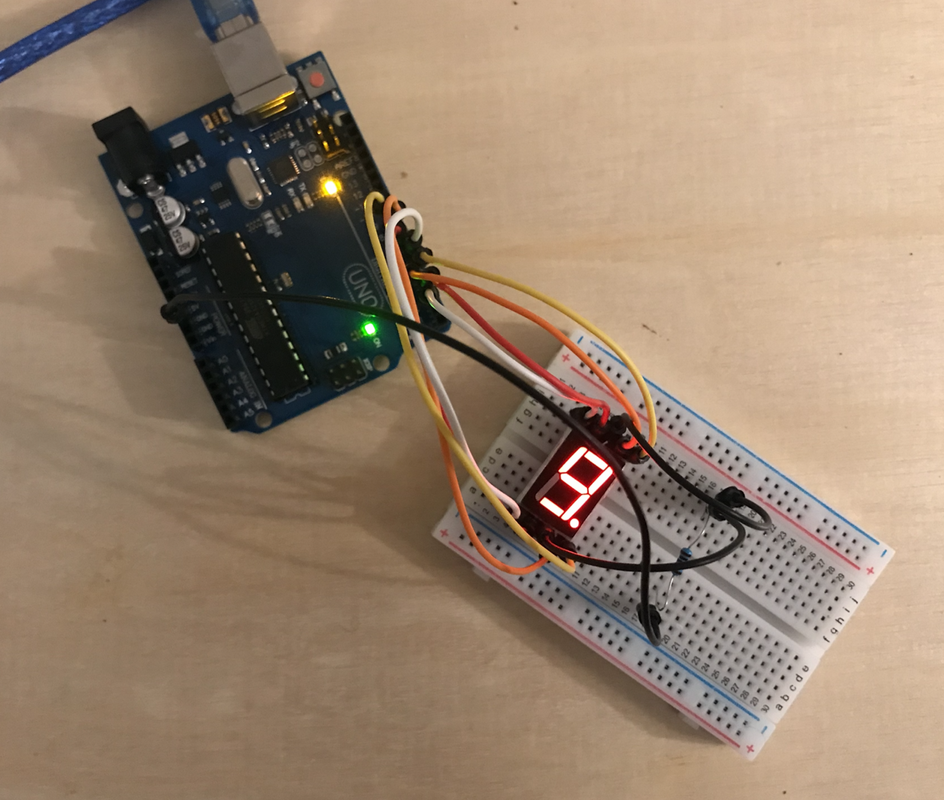
Welcome to #BuildwithRushi's second episode, I hope you are doing well. Today, we will be designing a Simple Count Down Timer using a Seven Segment Display, and the Arduino UNO board (used for power/voltage). Get excited for this one!! Also, I was looking back at last week’s tutorial on the DAC, and I realized that I could be more organized with these tutorial videos, and provide more context and steps instead of straight up jumping into the tutorial (my apologies if that seemed confusing!!), so that we can all learn from it!!! Thank you and enjoy :)
For the layout of these project “posts” on this page, there will be a short tutorial where I explain the process of building (link is above), and over here I’ll be writing about the planning/thought process, how the circuit works, and anything we can improve on..etc. If you want to follow along and look at the details of the building process, watch the tutorial and then read the rest of this post. It’ll make much more sense, and I encourage you to try it!! HAVE FUN!
Introduction
Materials I Used
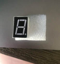
Planning and Thought ProcessWe have used count down timers so many many times for different purposes. The count down timer system we will be designing today will count down from 9 to 0 (Yes, its a very short duration), because I am using only one seven segment display, which can only display a single digit number (in decimal). However, there are 4 seven segment displays, which can display up to four digit numbers, so you can totally experiment with these as well! For today, we will stick to the single digit down counter from 9 to 0 (just to make things a little simpler :)).
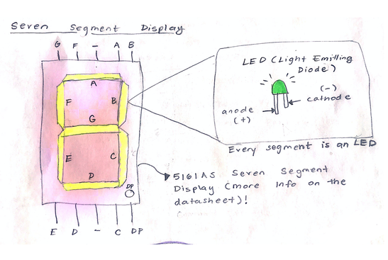
So how does the seven segment display work? The display is made up of 7 different LEDs (8 including the decimal point). An LED (Light Emitting Diode) is a semiconductor device that converts electrical energy to light energy. It can be used to display information (like on the seven segment display), detect transmission, and most importantly, emit light! The picture below describes the seven segment display circuit. We won't be using the decimal digit, since we are displaying whole numbers, but you can also integrate multiple displays to represent rational numbers as well!
ConclusionThank you, and this is the link to the code: https://github.com/aarushiramesh/Build_with_Rushi/blob/master/count_down_timer.ino I once again had lots of fun building and filming this, and I can’t wait for the next one --trust me, its gonna be great!! I’ll be posting the second episode next Saturday, May 9th. Stay safe, stay home and wish you happiness and peace! Hope you enjoyed it! :) 1. Building a DAC: Arduino ProjectApril 25th, 2020 - Episode 1
Welcome to #BuildwithRushi’s first episode! For this week’s building project, we will be designing a Digital to Analog Converter using the R-2R Ladder circuit and Arduino UNO board/a microcontroller interface! If you don’t have a board, no worries!! The board is used to input in signals and output signals from our DAC. The main part of this project is building the circuit, so have fun with that :) This was such an interesting project to work on, I learned so much from it!!! Hope you do too!
For the layout of these project “posts” on this page, there will be a short tutorial where I explain the process of building this DAC (link is above), and over here I’ll be writing about what I learned about, any challenges I faced during building the DAC, or anything we can improve on..etc. If you want to follow along and look at the details of the building process, watch the tutorial and then read the rest of this post. It’ll make much more sense, and I encourage you to try it!! HAVE FUN!
Introduction & Materials I UsedBecause I've been pretty intrigued by DACs and how they really work, I wanted to go ahead a build a simple implementation of it! A DAC is a system which converts a digital signal to an analog signal. If you want to know more about DACs and their applications, I've talked a bit more about that here.
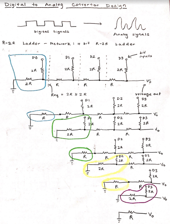
We are going to be designing a Digital to Analog system by building a circuit called an R-2R ladder. This circuit converts high/low voltage outputs (binary weights - with 1 referring to 5V and 0 referring to 0V) to an analog voltage (like 4.6777 or something). It accomplishes this through circuit analysis and voltage division. (we will get into this more later)
About the Arduino UNOSo first off, what is Arduino? Arduino is an open-source hardware platform, where you can program a microcontroller board to read in inputs, light up an LED when you push a button, or even to run a motor for a robot! The microcontroller is part of the Arduino board, and to feed it a set of instructions you need to use the Arduino programming language and its Integrated Development Environment, or its Web Editor. I’ve been so drawn into Arduino lately, especially because it opens up so many possibilities when it comes to projects, and it is easy to use and learn as well! This actually marks my second project with this board, so I’m kind of a newbie to it, but I LOVE IT!!!
The board that I’ll be working with is called an Arduino UNO board. The UNO is the first board in the Arduino board series, hence the name “UNO”! I definitely learned about the hardware design/parts of this board. 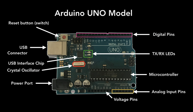
Some of the main parts of this board are the Digital Pins. The Digital pins can serve as output or input pins. When used as output pins, they can act as power/voltage sources. When used as input pins, they take in signals as digital input! We will be using these pins to build our digital to analog converter, since we will need digital inputs to convert them into continuous analog form!!
Another important part of the UNO board is the TX/RX LEDs. These LEDs indicate whether the UNO is transmitting (TX) or receiving (RX) data. When it's transmitting data, the TX LED blinks and when its receiving data the RX LED blinks. Planning and Thought ProcessThere are actually multiple ways to build a digital to analog converter, but implementing a circuit called R-2R ladder is a popular and an effective method (and it seemed ideal to implement since I have breadboard and resistors). The R-2R ladder circuit is a configuration of resistors in a "ladder like" format, which take in binary weights (bits) as inputs and convert them to an analog voltage. There are many advantages to implementing an R-2R ladder for a DAC. Some of them are:
This calculation gradually continues (as you can see from the highlighted circles appearing over and over again) until we are left with an output resistance or R, with Vout, being the output voltage (what we want). This goes back to the point where I mentioned about it being easy to calculate -- the output resistance is always R regardless of the number of bits, which is why the ladder configuration is very efficient.
I decided to go for a 4-bit DAC (just like the one shown above), meaning our system will take in 4 bits (the binary weights) through 4 digital input pins (D2, D3, D4, D5) on the board. The DAC system then outputs the analog voltage and we will be outputting this into the Analog pin (A0) of our board. I used the 1Kohm resistors for R and 2Kohm resistors for 2R.
ConclusionLets gooooo!!! I had lots of fun building and filming this, and I can’t wait for all of you to see what’s coming next! I’ll be posting the second episode next Saturday, May 2nd. Stay safe, stay home and wish you happiness and peace! |